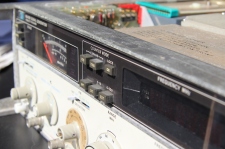
I recently acquired a HP 8640B signal generator. A quick summary of the specs shows why this is an interesting piece of equipment:
- 500kHz to 512 MHz (option 2 adds a doubler, extending the range to 1.024 GHz)
- Available power range is -145dBm to +19 dBm, withing +0.5dB across the full frequency range
- Extremely low phase noise (less then -130 dBc at 450 MHz, 20kHz from the carrier)
- Fine tuning (when in locked mode): >+/-20ppm
- Integrated counter, switchable between the internal generator and an external input
- FM and AM modulation
- Beautifully engineered (but that’s just an opinion)
The retail price in the mid seventies was around 12.000 USD.
My unit has the frequency doubler (Option 2), and a serial number starting with 1522U, meaning it was produced in 1975 (add the first two digits to 1960), week 22 in England. As far as I know this is probably in a factory in Erskine, Schotland.
And obviously it doesn’t work as it should. At first sight, the apparent issues are:
- The unit has cracked gears (which is a common issue)
- Intermittent power rail faillures
- Counter shows all zeros (seems to work with external signals when the -5.2v rail comes on)
- No output power on the front connector
- “Reduce FM vernier” is lit
At least, the display shows something, and there are some lights. More lights = better.

It needs cosmetic work as well: there is flash corrosion all over the metal parts, and some kind of brown gooey residue. One of the modulation dials has a broken knob. Plastic has yellowed, the vinyl needs work. The list goes on.
First issues to be solved (apart from cleaning while waiting for components):
- Fix -5.2V power rail (A18U1 needs to be replaced)
- Replace burned diode on the A12 Rectifier board, possibly using an external rectifier placed on a custom made board
- Zener diode A20VR3 (+44.6V LED) seems to have been burned, or is at least moving in that direction
After those issues have been solved, the RF path can be checked.
The following sources of information have been of great help so far:
- The people at the great Yahoo HP/Agilent Test Equipment newsgroup
- Various blog posts, I will list them where apropriate
- The US Army TM 9-4935-601-14-7&P “PATRIOT AIR DEFENSE GUIDED MISSILE SYSTEM” Operator, organizational, direct support and general support maintenance manual


