I’ve been working on my wireless tally system for a while now. Apart from the connection to the camera (for which I want to use a different connector to alter the appearance of the camera as little as possible) it is finally finished. Looking back, this has taken me much more time than I expected. But as this was the first project that I wanted to do in a more professional way instead of just throwing something together that shouldn’t necessarily be a bad sign. I’ve tried to keep revisions of the schematics, board design and code, as well as a clear BOM that can be used as a guideline in the future, should the need arise.
But first some background as to what the idea behind this project was.
When using different cameras to record any live set (be it show, television, concerts,..) it is important for a cameraman to know when his camera is selected and recorded or shown on screen. He then knows to keep his framing, or do whatever he is supposed to do during the shot. While most systems use an intercom to let the director talk to the crew, it’s not really a good option to have him cue every shot to the camera crew. Also, there might be a talent on stage that needs to know what camera to look into during a presentation.
Enter a tally system. That red light on top of television cameras? That’s a tally. Depending on the configuration it might be a red light in front of the camera, at the back, in the viewfinder or any combination of those. The signal comes from the mixing console and is usually relayed to the cameras by a dedicated connection in a multicable or embedded in a muxed signal on a triax cable.
But what if you can’t or don’t want to use an expensive triax or heavy multi cable? Imagine running the cameras on battery power, sending the video signal wireless, or just prefer to have only one cable running to the camera for the video signal?
On smaller shows, this is often a trade-off: more mobility for the camera people, faster installation, less cables and cheaper (non-studio) cameras can be used.
The wish-list was:
- Small
- Portable
- Easy to install/operate
- Good reception, preferably with an option to extend the wireless signal if necessary
- Adaptable in the future for different cameras or mixing desks.
As I have no proper background in RF design I opted to use available modules and early on decided to use Xbee modules from Digi. The Zigbee protocol is used and the modules are running in transparent mode. This has the advantage that the modules themselves take care of the routing and relaying of data, even if one of the modules/camera would be out of reach of the base station.
I decided to use the same microprocessor for both the senders and the receivers. After thinking about possible future additions I ended up picking the PIC16F721. While this chip has more options than strictly needed, I prefer to know a couple of micro controllers pretty well and use those. It has two 8 bit timers, one 16 bit timer, an ADC, SPI, I²C and UART modules as well as an internal oscillator and can operate with a supply between 1.8 Volts and 5.5 Volts. Pretty versatile.
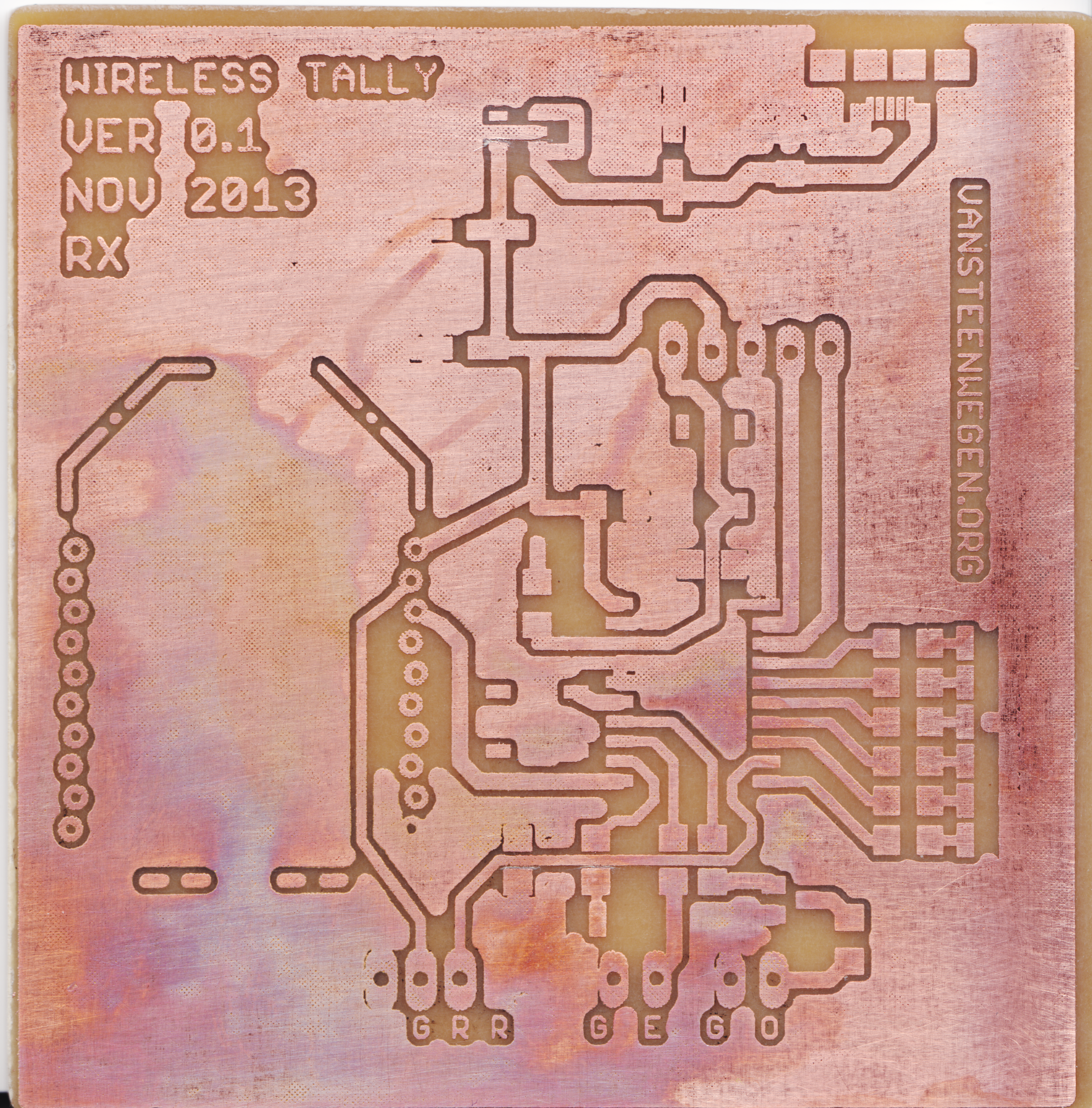
After drawing a schematic in Eagle I started with the board design. To keep things somewhat compact I choose to use all SMD components, apart from the Xbee modules. SOIC chips and 0805 components are really not that hard to solder, as long as one has access to a decent soldering station, good lighting and some kind of visual magnification (good loupe, stereoscope,…). Instead of using batteries and having to design a charging circuit as well I wanted to make the system modular. As more and more wireless transmitters for video signals are using regular USB for power, I opted to do the same. Mated with a portable USB charger such as these ones, one has plenty of power available for the tally, transmitters and other possible additions on the camera. When not in use these can be used for plenty of other purposes as well.

The first revisions had a micro USB connector, but after a while we decided to go for a bit more robustness and just wire a USB cable to the board. The footprint for the connector was kept on the board, so if the need ever arises it will be easy to solder it in.
I also needed a way to interface with the camera. The user manual has the pin-out for the studio connector. The tally input is on pin 2. When pulled to ground this enables the tally lights. After some help on the EEVblog forum I got the datasheet for the connector (site in Korean) used by JVC. After searching for a vendor for these connectors as well as contacting JVC they turned out to be almost impossible to order in reasonable quantities.
I first started trying to mould my own connectors based on the data from the data sheet and the connector in the camera.


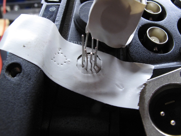
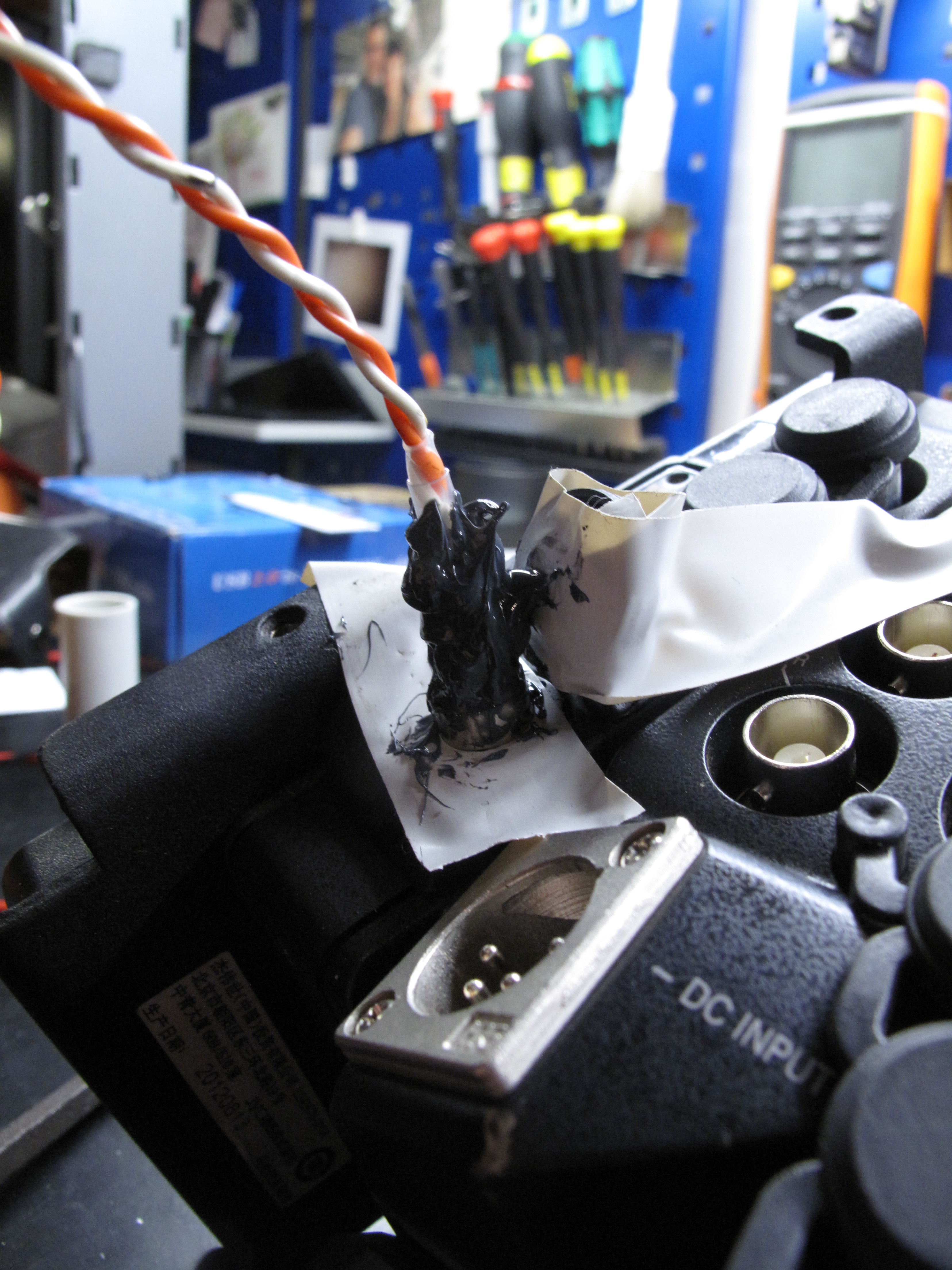

In the end this turned out to be beyond my capabilities :). The self-made connector was always too brittle, had too much friction, didn’t provide a reliable contact, … It was also a hideous contraption.
I ended up opening up the camera and adding a small breakout cable to try the system first.


Now that the system has been tested and proven to work reliably in the field, I’ve ordered these connectors from Binder to replace the connector in the camera. They should be a nice fit, are sturdy and can be locked when mated. This way I can also make my own mating cables.

Time to assemble the units.

I chose these enclosures as they are rugged enough, easy to open and fit the boards nicely (after some modifications on the board layout).
While assembling I realised I had forgotten to buy the correct spacers. I ended up cutting some small plastic tubing (such as used for aquarium pumps) to length and sliding it over the bolts. Works just as good.


If anyone is interested I’ll put the BOM, schematics and board files as well as the hex files for the microprocessor up for download. If I succeeded in documenting things the way I think they should, (most) things should be self-explanatory.
