I recently acquired a fairly well preserved HP 8711A network analyser. As sold, this is an economy model, offering only scalar measurements (although vector information can be acquired through the HP-IB bus).
Conversion
What makes this unit interesting, is that the hardware is the same as the never released 8712A, which has vector capabilities. Some changes in the bootrom allow the user to “convert” the unit, making it behave like a full fledged VNA.
Credits for this rom modifcation go to Massimo Porzio (IK1IZA). As far as I know, he is the one who took the time to figure this out. I also found a lot of information on the site of Michal Lewczuk (SP2XDM).
Before doing anything, a backup of the correction constants was made to disk.
Unit boot screen as received:

I used the TL866 USB High Performance Programmer which can be bought online for around €40. Download the software while you wait for the package to arrive, download speed reminded me of the late nineties…
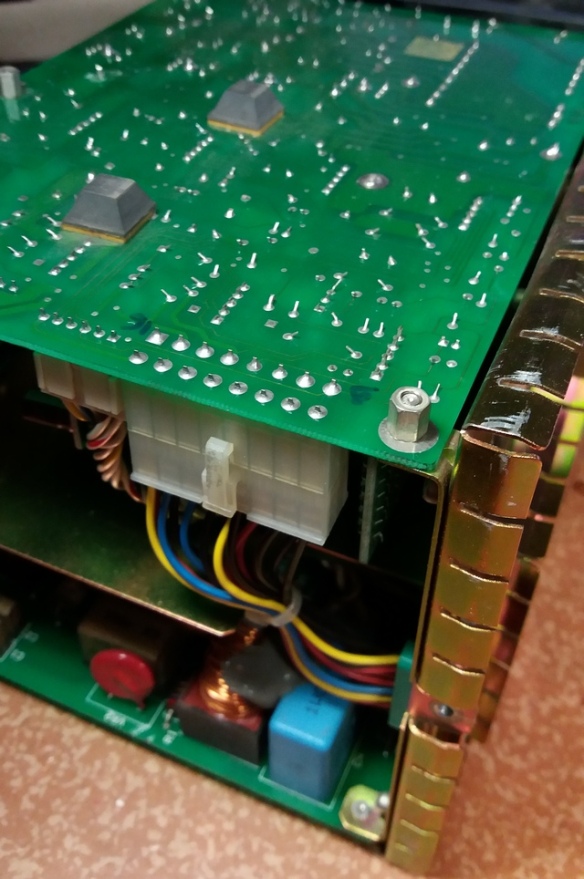
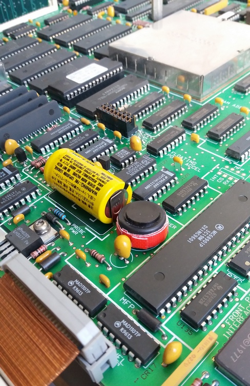
The bootrom with attached label (on the A1 CPU board, removal of the CRT/PSU module is necessary):

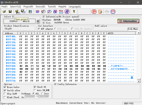
Contents of the ROM at address 0x1FFA0 prior to modifications:

After modifications:
New bootscreen (SRL and fault location enabled as well):

Smith chart as proof of vector capabilities:

CRT realignment and brightness setting
Some adjustments on the CRT were done:
- When looking from a normal viewing angle with the unit placed on the desk, the alignment of the options on the right of the screen seems “off” when compared to the location of soft buttons next to them.
- The screen was rather dim.
- Sizing of the display compared to the cutout in the front panel could be enlarged.
I marked the locations of the front panel cutout and the top and bottom buttons on the CRT:

After disassembling the CRT/PSU module and attaching the PSU to the back, followed by some creative cabling, the unit was powered on while leaving access to the alignment potmeters:

The positions of the potmeters before adjustment were marked:

After adjusting the height/width and brightness, the screen looked much better.
Power supply patch
According to a ECN from HP, units with serials between A00000 and 3325A00941 need a 3W, 680Ω resistor between pin 9 and 16 on J5 in the power supply.
Before:
Resistor added and pcb cleaned:

Speaker “modification”
The A models of this network analyser had an issue where noise would get into the audio circuit, causing a high pitched, squeeling noise. When used in a silent environment this was really bothersome, so I first tried replacing the speaker by a version with a slightly different resonant frequency.
This didn’t help enough, so I ended up with this ugly (but fully working) solution:
Cleaning and restoring the unit
A lot of time was spend cleaning and restoring the unit, as to give it as much of its original appearance as possible.
- The inside of the case was cleaned, connectors on the backplane (which are notorious for causing problems with this model) were cleaned using a combination of MEK, IPA, soda, warm water, patience and lots of love.
- Front panel and keypad were cleaned, and the yellowing of the plastic due to age and UV was reversed through the use of high concentration hydrogen peroxide. Dents, holes and cuts were fixed.
- The vinyl was cleaned, restored and treated.
- Internals of the disk drive were cleaned.
Documenting this is worth a separate post.

Bedankt voor de post Dieter! Knap gevonden, zal ernaar teruggrijpen als ik eens een zulke vind op een hambeurs of zo. 73 Bert, ON3VB
Heb de mijne (na zoeken) gevonden, in goeie staat, voor €400. Heb dit trouwens niet zelf uitgevonden, heb dat ondertussen toegevoegd…
Toevallig van de partij uit de rand gemeente van Antwerpen (zuid)?
Ik heb toen die HP 8711C (s) gekocht.
Als jij uit Nederland komt zou dat wel eens kunnen ja…
VNA mod werkt trouwens ook op de 8711C, moest je willen…
Klopt…..jammer dat bij die A de voetjes niet meer zaten.
Als het meezit zit morgen de Vector en optie 100 erin.
Heb het impedantie probleem opgelost met 2 Mini-Circuits UNMP-5075+ pads scheelt je wel ca 11 dB.
In de transmission connector zit een weerstand van 25 Ohm dus als je die vervangt heb je in ieder geval die kant wel 50 Ohm.
De reflection kant is in zijn geheel 75 Ohm (daar moet ik nog een oplossing voor vinden)
Heb dezelfde minimum loss pads op de kop getikt, je bent inderdaad wel een dike 12dB kwijt. De hardline van de A3 assembly naar de front connectors is ook 75 ohm dacht ik, niet? Vraag me af of je er geraakt met enkel die 25 ohm weerstand weg te halen. Het is te proberen natuurlijk…
Als je binnen een (heel) beperkte band blijft zijn er wel impedantie transformers die pakken minder verlies hebben, maar dan heb je natuurlijk een heel beperkte bandbreedte…
Hoi,
Heb met een andere VNA gemeten en die rechterkant is 50 Ohm (gehele rigid losgenomen en weer afgesloten met mijn cal load)
Meet maar met een Ohm meter de rechter connector door je zal zien dat je 25 Ohm meet.
De linker rigid heb ik op dezelfde wijze getest en die maakte geen contact met de 50 Ohm SMS connectoren de binnen kern is dunner (dus 75 Ohm)
Ook zal je zien dat de linker connector slechts een doorverbinding is.
Deze HP 8711C is vandaag ook een HP 8712C geworden.
Tevens heb ik ook een 8.4 Inch VGA scherm besteld via Ebay (zie EEVBLOG) en die wil ik er ook gaan inbouwen.
Een stuk zwaar wegend groen oplichtend glas is niet meer van deze tijd en door het nieuwe scherm krijgt de analyzer een stukje moderner uiterlijk.
Wist niet dat de CRT-LCD mod ook ging voor deze.
Krijg je dan je signal via de connector achteraan? Dan heb je nog een conversie van PAL naar RGBHV nodig, of niet?
http://www.eevblog.com/forum/testgear/upgrading-the-hpagilent-8714c-from-green-crt-to-color-lcd/
Heb hetzelfde scherm besteld en de 3 coaxjes voor de RGB heb ik al naar voren gehaald.
Ben benieuwd of dat bij jouw analyzer ook gaat (lukken).
Met vriendelijke groet,
Marcel
Hey Marcel, die thread had ik ook al gevonden maar de 8711A heeft geen VGA out maar enkel composite. Vandaar mijn vraag naar de composite naar RGBHV conversie. Blijkbaar heeft de C behalve een netwerkpoort ok nog een VGA aansluiting.
Misschien moet ik eens proben op de print of er ergens toch nog iets te vinden is, maar ik vrees er voor.
Misschien moeten we verder communiceren via email?
Beste Dieter,
Goed idee, mijn email adres is je waarschijnlijk al bekend, zo niet dan geef ik je het alsnog even door.
Met vriendelijke groet en in afwachting van je reactie,
Marcel
Hallo Dieter,
Kan jij mij nog even je mail adres opnieuw sturen?
Zit bij een andere internet provider.
Met vriendelijke groet,
Marcel
Hi there,
I’m Massimo IK1IZA.
I wrtite this post, just to inform you and any other who want to apply the mods to an HP8711C, that this FW mods don’t work on it! (on the HP8713C they works anyways).
To make them work on the HP8711C, you must change the first two bytes on the second line of configuration record from FFh, FFh to 00, 01h (the one that in the photos above were at addresses 1FFB0h and 1FFB1h, for a 16 bytes per row hex editor such the one in the photos above, they are the ones under the bytes with value 02h and 04h on the first configuration record line).
Leave the other FFh bytes as per the HP8711A mods.
Have a great day.
Massimo – IK1IZA
Hoops!
I just realized that I wrote:
“Leave the other FFh bytes as per the HP8711A mods.”
No! It was intended:
“Leave the other 00h bytes as per the HP8711A mods.”
Sorry.
Massimo
Hello Massimo,
Thank you for your comment! Great to hear that it can work for a 8711C as well.
I`m sure a lot of people are very grateful to you for your help, tips and comments.
I think you are also the one who assured me that the squeeling noise I heard on my unit was perfectly normal for the earlier models. If not for you I could have spent a lot of time searching for an issue/problem that simply didn’t exist.
My next projects will be a HP 8640B restoration, the BITX40 with some mods and learning CW. I’m still searching for SA bargain (but I’m not the only one, of course…).
Thanks and 73’s,
Dieter ON4DD
Hi Dieter,
I didn’t read you message until today because for a strange reason I had not any notification about it.
Anyways, I’m glad reading that my time spent on this is still useful for someone.
I wish you the best enjoyment doing all your next projects and I hope everything will be right at the first try (even if Murphy’s laws usually tell a different story, sigh!).
Have a great day.
73
Massimo – IK1IZA
Massimo, very interesting reading, just got hold of a 8711c wich i plan to modify according to your findings :-)
Is there a way to get your services by any chance if i send you the contents of my rom via e-mail, if you can look at it and send it back to me edited?
Also some of the guy´s talk about changing the impedance from 75 to 50 Ohms, i have had a dicussion with Agilent which states that it´s just the connectors and hard coax lines that is 75 Ohm, but that they are spot welded to the receiver board and hard to get out, otherwize it would not be a problem changing the system from 75->50 Ohm..
73´s
and best regards
Anders
( Sm7Hce )
anders@lm-konsult.se
Hi Anders,
yes, if you send me the binary content of your bootrom (or better bootflash), I can do the mods for you.
Even if it’s just a precautionary principle, I suggest you to keep the original bootflash chip until you see the instrument working right with the new bootflash. For this, If I were you I would buy a new flash chip and use it for the mods keeping the original in the drawer :-)
Unluckily (AFAIK), the 75 ohms machines have a different frontend indeed. Now I’m at office and I’ve not here the schematics, but until at home I could take a look to them and see if I remember correctly or not about that.
If you already don’t have the schematics, I’ll send them to you.
Always if I remember correctly, the schematics refer to version B of the family, but an HP engineer ensured me that except for the later ES version the only changes between versions were about the CPU board.
Have a great day.
Massimo
Thanks Massimo, and yes, i would also suggest putting the new program on a new chip :-), otherwize “murphy” will be there
– Assumption is the mother of all F-ups :-):-)
i appriciate the offer to do it for me, and i will take you up on that, i just have to find a suitable programmer to use… puhh, must have been 20 years ago one used something like that – any suggestions?
According to the tech i talked to, the only difference between 50/75 Ohm is the connectors on the motherboard (wich are spotwelded he claims) the “hard” coax and the frontconnectors, otherwize its all the same.. ofcourse one can change them to coax but then there probably will be some losses and frequency problems further up 1Ghz,…. really good cables are hard to find….
Please send me the schematics = very nice :-), dont have them yet, saw something on agilents web page, but havent downloaded anything ..
– And if you can send me a e-mail so i know where to sent the file
I wish you and the rest of the gang, a wonderful evening
Best regards
/ Anders
one thing that stroke me, is the 8711,12,13,14 basicly the same unit or have they fitted a wider oscillator on the 13&14 for 3Ghz… or is this also software?
Hi Anders,
I just sent you the schematics via the WeTransfer service because their size were huge (abt 90Mbytes).
Take a look to your mailbox for the instructions to download them.
The link for download it will be there for the next 7 days.
Effectively despite the 50 ohms and 75 ohms receivers have different schematics numbers, the schematics looks the same to me.
The 1.3GHz machines have a completely different synthesizer board and couplers, so unluckily it’s not just a SW difference.
Have a great day.
73
Massimo IK1IZA
Hi Massimo, got the files, thank you :-)
i kindda figured that was the issue with the 3Ghz models, i´ll get back to you shortly
thanks
73
Anders
Hi Anders,
enjoy your task and have a great day.
By the way, I think that the following link should be available in the next 7 days to anybody who needs the HP871xx schematics.
https://we.tl/p90SwKxPCr
All the best.
73
Massimo
Anders,
If you ever get around to adapting your unit to 50 ohms, please let me know. That would be great.
Regards,
Dieter
Hi Dieter, i certanly will let you know :-)
Have a nice weekend
Best regards
/ Anders
Hi Anders,
I thought a little more about the 50/75ohms conversion.
And effectively, there is no reason to have different receivers for the two versions because they are coupled to the instrument ports via directional couplers, which coupled line has no need to have the same impedance of the coupler passing through line.
You should take a look to the source output stage and the couplers themselves. I guess they should be impedance related components indeed.
The source could have a minimum loss impedance matching adaptor at its output.
While the couplers could be different in the main line and termination loads.
By the way, some times ago I tried the Smith chart 75ohm measurement using a couple of 50/75ohms adapters. Well, after having done the port calibration to de-embedding them, I had been able to work without appreciable issues.
Have a great day
Massimo
Hi Massimo
Yes i agree, i´m using the 11852A low loss pads for my unit wich works just fine after calibration, you just loose approx 6db in signal, but i doesent make much difference in my case, so why am i interested in the conversion…
– Because its fun :-):-):-)
Many systems are the same due to R&D costs and it´s of course cheaper to put this in software rather then new hardware when designing, and i appriciate this, however when we are dealing with 25 year old systems that is discontinued, it´s fun to play around – i personally cannot afford to take my hobby to the 50.000 Euro level to buy a new one so…..
I will definitly check out the schematics and se if there is a “fix” for it, it seems that there is some interest for this in the community to :-)
BTW – wich reader/programmer do you use for this eprom? – have to “shop around” worked many, many years ago with servicing home computers, vcr´s etc.. and at the time we had a station for this, but this is now long gone and if it still exists it is probably a PET bottle or something by now :-)
Have a nice evening
73
/ Anders
Sm7Hce
Hi Anders,
sorry for the late reply, but yesterday I spent my time fixing my Rohde & Schwarz SME03 LCD. It had the endemic horizontal black lines issue. Those times the LCD frontal metallization lines were connected through a damned thin plastic flat ribbon just attached with am adhesive tape on the controller PCB and with a glasslike glue on the LCD!
The issue is unsolvable for me, so I bought for few Euro a working CMD57 (a useful for nothing else than as an GSM repairing instrument) and executed an LCD “transplant”.
You wrote:
“– Because its fun :-):-):-)”
I fully agree, the expensive instruments are just for professional use, let the companies buy them and let us buy their “oldies” for few bucks.
Most (practically almost all) of my home workshop instruments had to be fixed (and sometimes hacked).
By the way, I recently bought an Advantest R3671 Signal Analyzer (13GHz SA + 3GHz digital SG) that I hacked to get a R3681 (32GHz SA + 6GHz digital SG). As you stated, the machines were the same and had just a serial EEprom on each board which other than the board settings and calibrations got the extensions limits hidden into the board name!
In that case everything works great, but the SA has the input attenuator limited to 15GHz so the SWR at the input isn’t so good at 32GHz. But I got it for free and the readings are into the specs up to 32GHz anyways, so who cares? :-)
For the bootflash I used a very old Needhams EMP10 programmer, but it’s a DOS only device. Dieter’s suggestion should be better, just look at the flash model of your NA to see if it’s supported, that because as far I know the chips changed version by version.
Have a great day.
73
Massimo
Massimo, great :-), it lookes like you and me are the same haha, i also have loads of refurbished equipment bought online at various auctions :-)
Just finished dissasembly of my 8711c, but it looks completely different then the pic´s ive seen online, lots of surface mount and 8712 board w. AM28f020 as boot rom, i´ll send you some pics to your mail, if this one looks the same in software i dont know, but i´ll need a different programmer :-( luckely i havent bought one yet
Your an radioamateur i guess, what are you using?
Best regards
/ Anders
Hi Anders,
I’m radio amateur, my call is IK1IZA but I’m little or not active in these days.
Every time I’m at my home workshop (like now) while I’m doing my task I listen to the local radio club VHF frequency,
Until last month I also had a three band home made delta loop, but after 26 years of its standing on the roof I had to dismantle it because of its age (everything passes sigh!).
About the Am28F020, Dieter’s suggested TL866 programmer supports it.
Anyways, my email is mporzio@teletu.it
Have a great Sunday.
Massimo
Hi again Massimo, i´m sending you the pics in 2min, are currently downloading my phones gallery wich took 30min.. :-) yes to the progrmmer, it only need to take the PLCC casing
/ Anders
Also, i´m thinking – these original coax hard lines are extremely accurate, if one just dealing in amateur frequencys, it may be ok to use some good coax cable, but one can very easy run in to problems like stray capacitance etc, when going further up the in the Ghz zone, so for those who try and change this it´s worth to know..
/ Anders
Anders,
I used a TL866, available for less than 40 euros online. Did what it had to do.
Dieter
Hello, ill try and see in i can find one locally, replied to Dieter about this before sorry :-) – have the PLCC casing on the AM
Have a nice day
If you are talking about the 8711 inner HL I don’t think they are critical indeed.
Just one consideration about the cables to de-embed for connect the DUT to the VNA.
Take always account that when you use cables which length is close to 1/4 lambda (corrected for the cable speed of course) for S11 the de-embedding works bad or it doesn’t work at all at 1/4 lambda. That because @1/4 lambda open, close and load as seen by the couplers are always matched.
(I write this because one time I’ve been deceived by the use of cables at that length, note also that the lenght I’m writting about is those between the inner coupler port and the cable end at which you move the reference plane by de-
embedding)
Again, have a great day.
Massimo
massimo
Hi Massimo, finally got the holder for the flash memory, i have sent you the files on e-mail
/ Best regards
/ Anders
Massimo,
I don’t really understand what you are talking about concerning the de-embedding of the DUT. Could you explain further?
Also, may I ask what you use the SA >15GHz for? What kind of circuits/systems are you working on?
Regards,
Dieter
Hi Massimo, finally got the holder for the flash memory, i have sent you the files on e-mail
/ Best regards
/ Anders
Hi Anders,
I sent you the modified file.
Let me know how it works.
Have a great day.
Massimo
Hi Massimo, we have sent you a mail :-)
Best regards
/ Anders
Thanks Dieter, i´ll se if i can find one locally :-)
Best regards
/ Anders
Sorry Dieter, i replied to you about the programmer from fozzywiz
/A
Anders,
Same person. Fozzyvis is an old alias. Just changed my settings to show my name instead of the alias.
Sorry about the double messages guy´s – keep on missing out who originated the message :-):-)
Hi Dieter,
I have an HP 8711A that produces a bootROM checksum error. Maybe the data is simply corrupted.
I have the same U83 version as you do (REV A.03.01). I found the bootROM code on KO4BB’s website, but wonder if there’s a way to load it to the ROM from floppy? If not, do you know if anyone sells programmed bootROMs for the 8711A?
Thank you and regards,
Mark Rumreich
Hi Mark, here attached there are the boot ROM images of my own HP8711A.
HP8711-U82_Original.bin was my original one (scalar only analysis) HP8711-U82_Full.bin is my current full optionals one
Take care that it has the serial number of my own of course, if you want to set your instrument serial ID, just overwrite the ten bytes starting @ 1FFF2H that now are set to 3325A00922. But since the instrument is from a long time unsupported, you can leave the serial ID as is.
Hope you’ll get it working soon, without other issues, in case feel free to contact me.
Have great days and happy new year.
Massimo
Best 73 – IK1IZA
I think that Mark’s question mostly was as to how to program the ROM chip itself? If so, it is rather straightforward using the kind of programmer I’ve used. If I misunderstood or if you have other questions, let me know…
Hi Dieter,
sorry this morning I really read too hastily your previous message.
Yes, as far I know there are no ways to program the bootrom via the floppy and the onboard programmer.
Mark has to use a separate programmer to burn that ROM.
Have a great day.
Massimo
Dear Massimo,
Thank you for your comments. I have used PROM burners in the past but don’t own one now. I was hoping to avoid buying one and setting it up. Possible options would be if the 8711A allowed modification of values through the floppy drive or manually through some service menu. Another option would be if programmed ROMS were available for sale. Are you aware of any of these options?
Regards,
Mark
Mark, I wouldn’t mind programming a rom for you but I can’t say for sure how long it would take me to acquire a blank chip and send it out. It might be much quicker to just purchase a programmer. Setting it up is just a matter of connecting the USB cable and installing the software. Say maybe 10 minutes.
Hello Massimo,
I have an HP8711C with the 28F020 ROM. I edited the rom to 00 00 00 01 as you suggested. It turns the instrument into an HP8730A (whatever that is) and complains not to be connected to a HP 87030 box (whatever that is). I’ve tried 00 00 00 00 and 00 00 00 01 and both result in the HP8730A. Any help would be appreciated.
Dear Massimo,
is it possible to send me a link where i can find the schematics from a 8713B and can these equipment also be upgraded to a 8714B
Also thanks into advance
Luc ON7KZ
Hi Luc,
here is the link to my MediaFire folder where yo can download the HP871xB schematics.
Note that unluckily the CRT control board and the PSU schematics are missing I have only the schematics version A of that blocks.
https://www.mediafire.com/file/nas52uetyyovpkq/HP871xB_Schematics.zip/file
Hope they help you.
Have a great day.
Massimo IK1IZA
Hello Massimo,
Thanks for the link to the schematics
greetings,
Luc ON7KZ
Hello Massimo,
I have an HP8711C with the 28F020 ROM. I edited the rom to 00 00 00 01 as you suggested. It turns the instrument into an HP8730A (whatever that is) and complains not to be connected to a HP 87030 box (whatever that is). I’ve tried 00 00 00 00 and 00 00 00 01 and both result in the HP8730A. Any help would be appreciated.
Hi Mark,
I’m at office now, and I don’t have here my notes about the mod.
Anyway, re-reading my post above I would try to set those bytes to FF FF 00 01.
I apologize for not having been clear in that post.
Let us know if that works.
Have a great day.
Massimo
I have tried:
ff ff ff ff
00 00 00 00
00 00 00 01
00 01 00 00
ff ff 00 01
ff ff 01 00
00 00 01 00
my email is optoguy@gmail.com
Hi Mark,
I finally checked my archive and retrieved the corrected pdf for patching th HP8711C (it happens only with this version of the VNA, because the HP8730 Tuner analyzer was designed for VHF tuners, so the HP8713C hadn’t it embedded).
The right byte sequence is:
00 08 FF FF
AFIK, the correct bytes function is as follows:
Bytes 4-8 The string “HP87*”
Bytes 9-13 all zeros (unknown)
Bytes 14-15 OPTION SWITCHES. Zeroing these bytes you enable all the features of the
HP8712 machine (For HP8711C machines, bit 3 of byte 15 when enabled turns the machine
into the HP8730 Tuner Analyzer, for this reason leave this bit to logic state 1 to get the
HP8712C full featured VNA)
B ytes 16-17 all FFh (maybe reserved option flags)
Bytes 18-27 The machine serial number in ASCII, as reported on the label attached on the back
of the instrument.
Bytes 28-32 Unknown
Anyways, I already sent to your e-mail the updated PDF of the mod, share it freely.
As always, let us know if it works here.
Have a great day.
Massimo
Bravo Massimo. It works! For those interested, I did this on a 75 ohm unit. I replaced the two connectors on the front with 50ohm versions and replaced the channel 1 internal cable to a 50ohm one. In scalar mode it works just fine with at least 90dB of dynamic range. In vector mode you can change the Z0 in the menu settings and change this to 50ohm. I need to spend some time with it. Thank you again
Hi Mark,
glad to be helpful.
For what concerns the 75 to 50 ohms conversion, to get a better result you should fit two minimum loss 75 to 50 pads behind the input connectors, leaving the 75ohm cables and making the calibration this way (after setting Zo to 50ohms of course). The VNA should work great also on the Smith chart. The only limitation will be the dynamic reduction due to the two minimum loss pads insertion.
Enjoy your instrument.
Have great days.
Massimo
Hi guy´s, i have 3 of these converted to 8712 and they work great, in my case i just use the HP11852A 75->50 Ohm impedance converter, in that case we have a both 50 and 75 ohm instrument just by changing in the menu and the converter, AND the correct connector for both 50 & 75 Ohms whenever needed.
Massiomo, thanks again for the conversion instruction – even if it was several years ago, and to you Mark – enjoy the instrument, it´s a really solid piece of hardware
Take care and have a great summer
BR
/ Anders
I think having three qualifies as one of the deadly sins…
Hi Anders,
yes, I agree with you.
The correct way to get a correct 50 & 75 ohms analysis the external minimum loss pads are state of the art.
In case one need the 50 ohms only, embedding the pads in the instrument frontend maybe a good choice to avoid damaging them. Anyways, a 75 ohm instrument has the detectors and the directional couplers tailored for the right Z0 to get the maximum dynamic from the instrument.
If I get it right, Mark changed the channel 1 connector and the cable to 50ohms, which is right anyways for the analysis (even vectorial after a calibration). But in case your DUT was sensitive to high return loss changes along its frequency spectrum, it could report slightly incorrect values because the 50 ohms line driven by the 75 ohms source behaves as a frequency dependant Z adapter, so in case the DUT is a non linear device could work incorrectly.
Have a grat day.
Massimo
Pingback: DIY active / HiZ / high impedance probe design. | Dieter Vansteenwegen (ON4DD)
Hi Guys,
I have a 8711a and looking to do the EEPROM. Is there a ptrobkem with enabling all features (aka 1E1 attenuator ) if the hardware has not been installed?
Thanks,
Brian
Hi Brian,
the only problem I could imagine is that the calibration function could behave wrong because of a -3dB offset introduced by the attenuator. The easiest way to workaround the issue should be insert a 3dB bullet on the output.
Anyways, you should set the output power between +13dB and -3dB only, avoiding lower power output set, otherwise the analysis would return wrong levels.
Have a great day.
Massimo
I was worried the digital control of the existing attenuator would be messed up. Has any figured which eeprom changes affect this option? I could start trying combinations but that’s going to take time I suspect.
It would be nice to find a failed unit I could salvage one. Having it is needed to test amplifiers. I wa think about putting a manual one in it.
Massimo,
Upgrade successful! The attenuator option is not enabled with the mod and the power control range was the same after the mod too. I measure the power before and after and no change. Next thing, replace the backup battery and thinking about replacing the floppy disk with a USB disk emulator. Has anyone tried the disk replacement?
Brian, KC4KK
Hi Brian.
My HP8711A which I used to hack the firmware had the 1E1 installed, so I couldn’t check if any of those bits was enabling it. I must honestly admit that I was trying to get all what I could get indeed, not worrying about the installed hardware.
Nice to know that finally you got it right. Maybe that option 1E1 is enabled automatically by installing the attenuator board, through the output level feedback measurement.
I hope you get fun from you new VNA ,
have great days.
Massimo, IK1IZA
Massing,
I think you are right on the HW must be sending signal when it’s installed.
Have you heard anyone replacing the floppy drive with usb floppy emulator?
Hi Brian,
About the floppy emulator: no, I didn’t hear anyone who did it.
But I used one of those devices in the past for a friend who had to do that on an old Unix based CNC machine and it has been easy to do there.
So, since the HP 871x was built over an Unix like OS I guess it should work indeed.
In case you’ll do thtat, let’s us know if it works.
I installed a floppy emulator (Gotek SFR1M44U100), it works, but mechanically, it is not easy to integrate, I think cable length/angle was the issue. I saved my constants, and put the original floppy back in.
Dear Massimo
Can i call you through viber or whatsup? or may be through mail?
I need your help
Thank you in advance
Nick sv1enq